Industries
Get direct access to our extensive portfolio of optical products and specialist technical expertise.

Choosing the right Single Phase 10v Rectifier begins with the real electrical conditions, not only the 10-volt label. A component marked 10 V may still fail if its current rating, reverse-voltage rating, or thermal design is unsuitable. The load matters.
Robert W. Erickson, a respected power electronics researcher and coauthor of Fundamentals of Power Electronics, stated, “Power electronics is the application of solid-state electronics for the control and conversion of electrical energy.” This principle applies directly here. A rectifier must convert alternating current safely and consistently, while managing heat, ripple, and electrical stress.
Start by checking the transformer output and the rectifier’s expected input waveform. Measure the load current during startup, not only during normal operation. A small motor or capacitor may draw a sharp surge. That detail is easy to miss. Then compare the diode bridge’s forward current with the measured demand, leaving practical safety margin. Examine reverse-voltage capability, forward-voltage drop, junction temperature, and package design.
A warm rectifier is not automatically defective. However, excessive heat often reveals an undersized part, poor airflow, or an underestimated load. A heatsink may help, but it cannot repair a wrong specification. Ripple voltage should also be measured with an oscilloscope, because a multimeter can hide short peaks.
Choosing by price alone is tempting. It is also risky. Datasheets may omit the exact installation conditions. Verify reputable manufacturer data, test the finished circuit, and document the measurements. The best Single Phase 10v Rectifier is the one that remains stable under real load, repeated starts, and imperfect operating conditions.
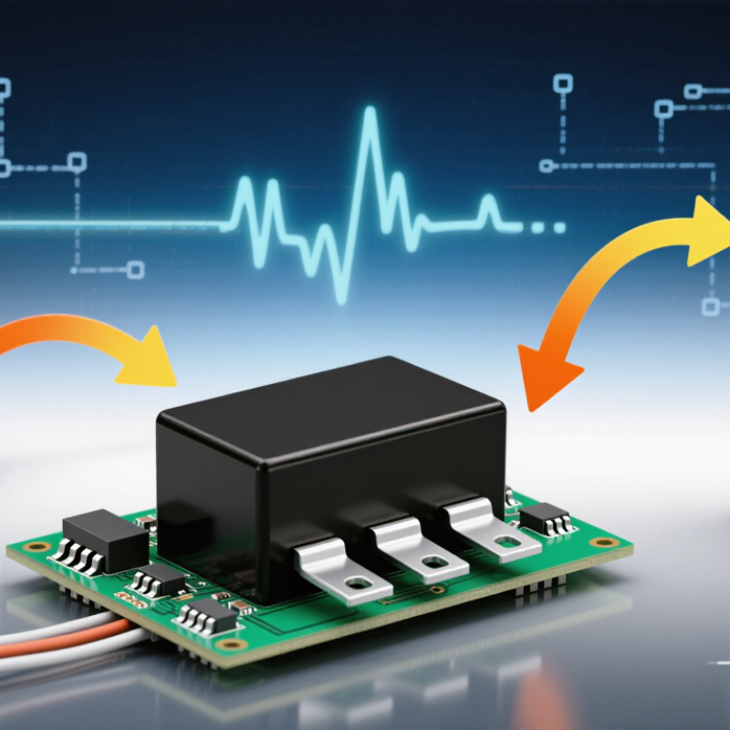
A single-phase 10V rectifier converts alternating current (AC) into direct current (DC) for small electronic circuits, control systems, and battery-related applications. It usually uses four diodes in a bridge arrangement. During each half-cycle, two diodes conduct and guide current in one direction. The output is not perfectly smooth. It contains ripple, which may affect sensitive equipment.
The term “10V” needs careful checking. It may describe the expected DC output, the transformer’s secondary voltage, or a diode voltage rating. These meanings are not interchangeable. A 10V AC transformer can produce more than 10V DC after rectification, especially with a smoothing capacitor and light load. Measure the voltage under real operating conditions. Also check the required load current, reverse-voltage rating, ripple tolerance, and temperature rise. A rectifier that works briefly may still fail during continuous operation.
Tips: Select a current rating above the normal load, preferably with practical headroom. Confirm polarity before connection. Add a suitable capacitor only after checking inrush current and diode limits. Keep wiring short and insulated. I have seen small rectifiers run hot because their ratings were treated as exact limits. That is an easy mistake. If the output powers sensitive electronics, measure ripple with proper test equipment rather than trusting the printed voltage.
Voltage and current requirements must be measured before selecting a single-phase 10V rectifier. Do not rely on the “10V” label alone. Confirm whether it describes the AC input or the rectified DC output. For a 10V AC transformer, the peak voltage can reach about 14.1V before diode losses. A capacitor-input circuit may therefore produce more than 10V DC without a regulator. This detail is easy to miss.
Check the rectifier’s repetitive reverse-voltage rating against the circuit’s highest possible voltage. Leave extra allowance for transformer tolerance, switching spikes, and brief surges. The current rating should exceed the load’s continuous current, not merely match it. Motors, lamps, and large capacitors may draw high starting current. A practical design often uses a 25% to 50% current margin, depending on cooling and duty cycle. Measure the load with a multimeter under real operating conditions. Laboratory readings can look reassuring, yet wiring resistance and heat may change the result. That deserves another check.
Tips: Identify the RMS input voltage first. Calculate peak voltage next. Consider diode forward drop. Check ripple under full load. Use a heatsink when temperature rises noticeably. Review the datasheet’s surge-current rating, too. A rectifier rated for 10A may not safely deliver 10A continuously without proper ventilation.րաժեշտ
The correct rectifier depends on whether 10V means AC input or regulated DC output. For a low-current control circuit, a standard full-wave bridge is usually practical. It uses four diodes and delivers twice-line-frequency ripple. However, two diode drops reduce the available voltage. Silicon bridges commonly lose about 1.2–1.8V, while Schottky devices may reduce that loss at moderate current.
Circuit design matters more than the diode label. A bridge followed by a capacitor gives simple filtering, but its charging pulses can increase input harmonics. IEC 61000-3-2:2018 defines harmonic-current limits for applicable equipment, while IEEE 519-2022 uses a 5% voltage-THD limit at the point of common coupling. These figures are not automatic guarantees. Measure the real installation.
For a 10V, high-current output, choose a low-forward-drop bridge and calculate heat using P = Vf × I. A 0.6V total drop at 2A still creates roughly 1.2W of heat. A center-tapped full-wave circuit can use fewer conducting junctions, but it needs a suitable transformer. Synchronous rectification can improve efficiency, though its control timing adds failure points. Add a buck regulator when load voltage must remain stable. Keep the loop short, place the capacitor close to the bridge, and verify ripple with an oscilloscope. I would not trust a simulation alone; transformer resistance, diode temperature, and capacitor aging often change the result.
How to Choose the Right Single Phase 10V Rectifier?
A 10V rectifier should match the circuit’s real load, not only its stated voltage. Check the required output current, reverse voltage rating, surge current, and ripple tolerance. A device rated for 10V output may still need a much higher reverse-voltage rating. Transformer peaks and switching transients can exceed expectations. Leave practical safety margin.
Current creates heat.
For a silicon bridge, two diodes conduct during each cycle. At 1A, a 1.4V combined drop can produce about 1.4W of heat. That power needs a clear path through the case, thermal interface, and heatsink. Measure the case temperature after thirty minutes under normal load. Then test the highest expected ambient temperature. A cool workbench can hide a poor design.
Reliability also depends on derating. Avoid operating continuously at the maximum current or temperature listed in the datasheet. Check terminal spacing, mounting pressure, solder quality, and airflow around the rectifier. Add suitable input protection when the transformer can deliver a strong surge. Verify output ripple with an oscilloscope, especially when a capacitor follows the rectifier. Calculations help, but they are not enough. A component may pass a brief bench test and still fail after months of heat cycling. I once underestimated enclosure temperature; the circuit worked, but the rectifier ran far hotter than expected. Recheck the design in its final housing.
| Evaluation Dimension | Recommended Design Reference | Example for a 10 V DC Output | Selection Guidance |
|---|---|---|---|
| Output voltage | 10 V DC nominal after rectification and filtering | A 9 V RMS transformer secondary has an ideal peak voltage of approximately 12.7 V before diode losses. | Allow for diode drop, transformer regulation, ripple, and load variation. Verify the minimum and maximum output voltage under actual operating conditions. |
| Rectifier topology | Single-phase full-wave bridge for a standard two-wire AC source | Four diodes conduct in pairs; two diode junctions are in the current path during each half-cycle. | A bridge provides full-wave rectification but generally has a higher forward-voltage loss than a center-tapped arrangement. |
| Average output current | Select the rectifier for the continuous DC load current, not only the nominal average value. | For a 1.0 A continuous load, a rectifier rated at approximately 1.5 A or more provides practical operating margin. | Check the datasheet conditions for the average forward current. Ratings depend on mounting method, case temperature, lead length, and waveform. |
| Peak repetitive reverse voltage (VRRM) | Use a rating comfortably above the highest reverse voltage that can occur. | For a 9 V RMS secondary, the ideal peak is about 12.7 V; a 50 V or 100 V class rating is commonly suitable when transients are controlled. | Include transformer tolerance, line surges, leakage inductance, and switching transients. Do not select VRRM from nominal voltage alone. |
| Forward voltage drop | Lower forward voltage reduces heat and improves voltage headroom. | At approximately 1 A, two silicon diode drops may total about 1.4–2.0 V; Schottky devices may be lower, depending on current and temperature. | Use the forward-voltage value at the actual operating current and temperature. Do not use the zero-current or typical-only value. |
| Surge or inrush current | The non-repetitive surge rating must tolerate capacitor-charging current and transformer energization. | A capacitor-input supply can produce a short, high-current pulse when switched on; the exact value depends on capacitance, source impedance, and starting phase. | Compare the surge-current rating with the expected startup condition. Add a fuse, soft-start element, or inrush limiter when necessary. |
| Ripple frequency | Full-wave rectification produces ripple at twice the AC line frequency. | 50 Hz input produces approximately 100 Hz ripple; 60 Hz input produces approximately 120 Hz ripple. | Use the correct ripple frequency when sizing the filter capacitor and estimating output ripple. |
| Filter capacitor sizing | For a capacitor-input filter, use approximately C = Iload / (fripple × ΔV). | At 1 A, 100 Hz ripple, and 1 V peak-to-peak ripple: C ≈ 0.01 F, or approximately 10,000 µF. | Verify capacitor ripple-current rating, tolerance, lifetime, and voltage rating. A larger capacitor can significantly increase startup surge. |
| Power dissipation | Estimate conduction loss using P ≈ 2 × VF × IDC for a bridge. | At 1 A and 0.9 V per conducting diode, bridge conduction loss is approximately 1.8 W before switching and thermal effects. | Use datasheet curves where available because VF changes with current and junction temperature. |
| Junction temperature | Keep the calculated junction temperature below the specified maximum with design margin. | TJ = TA + PD × θJA, or use the complete case-to-heatsink thermal path. | A lower thermal resistance and adequate airflow reduce junction temperature and generally improve long-term reliability. |
| Thermal resistance | Evaluate θJA, θJC, and θCS according to the mounting arrangement. | A 2 W loss with a total thermal resistance of 20 °C/W creates approximately a 40 °C temperature rise above ambient. | Do not apply a free-air thermal rating to a PCB, chassis, or heatsink installation without checking the specified conditions. |
| Ambient temperature | Calculate performance at the maximum enclosure and local ambient temperature. | For a 50 °C ambient and a 40 °C calculated rise, the estimated junction temperature is about 90 °C. | Include nearby heat sources, restricted airflow, altitude, and enclosure temperature in the thermal assessment. |
| Reverse-recovery behavior | For low-frequency mains rectification, reverse recovery is usually less critical than forward loss and surge capability. | At 50/60 Hz, standard rectifier diodes are commonly suitable; faster devices may be useful where wiring inductance or high-frequency switching is present. | Select a fast or ultrafast device only when the circuit waveform requires it, since switching behavior and leakage may differ. |
| Leakage current | Check leakage at the maximum rated temperature and reverse voltage. | Schottky rectifiers typically have higher reverse leakage than comparable silicon PN diodes, especially as temperature rises. | Consider leakage when standby power, output discharge time, measurement accuracy, or high-temperature operation matters. |
| Electrical safety and isolation | Use an appropriately rated isolated transformer or certified isolated AC source where safety isolation is required. | A 10 V output voltage alone does not make a non-isolated mains circuit safe to touch. | Check creepage, clearance, insulation system, fusing, enclosure, and applicable safety standards for the complete assembly. |
| Reliability validation | Validate voltage, current, temperature, surge, and endurance under worst-case conditions. | Test cold start, hot restart, maximum load, minimum input voltage, maximum input voltage, blocked airflow, and repeated power cycling. | Use traceable datasheets, production test limits, sample testing, and documented derating rules rather than nominal ratings alone. |
Choosing a single-phase 10V rectifier starts with one basic question: is 10V the input or the required DC output? Check the datasheet carefully. A rectifier producing 10V DC may need a higher AC input, especially after voltage drops and ripple.
Installation needs affect more than mounting space.
Measure the load current, duty cycle, and available ventilation. A bridge rectifier running near its limit can become surprisingly hot. Leave room for airflow, secure the wiring, and protect exposed terminals inside a suitable enclosure. Use a correctly rated fuse near the power source. Confirm polarity before connecting sensitive equipment.
Safety deserves practical attention.
Verify insulation, grounding, and isolation requirements against local electrical rules. Add filtering only when the load needs stable DC, because capacitors increase startup current. During testing, use a meter and inspect the unit after several hours under normal load. Small details matter.
Total cost includes more than the rectifier itself.
Include a transformer, fuse holder, enclosure, heatsink, terminals, wiring, labor, and future replacement time.
I once underestimated heat management on a low-power project, and the extra enclosure work cost more than the rectifier.
A cheaper part can also require thicker wiring or additional cooling. Compare the complete installed system, not just the catalog price. Some assumptions will still need checking on site.