How to Choose the Right Fiber Transceiver?

Choosing the right fiber transceiver is no longer a simple matter of matching speed and connector type. Network traffic keeps growing, while data centers demand lower latency, higher density, and tighter power budgets. Cisco’s Annual Internet Report projected global internet traffic to reach 5.3 zettabytes per year by 2023. That pressure affects every optical link, from a short server connection to a metropolitan backbone.

A reliable fiber transceiver decision begins with the physical environment. Check the switch port, transmission distance, fiber type, wavelength, and operating temperature. An OM4 multimode link may support 100G SR4 across 100 meters, while a single-mode 100G LR module commonly targets distances near 10 kilometers. The actual result depends on connector cleanliness, insertion loss, polarity, and the installed cabling. Small details matter.

LightCounting’s optical communications market reports continue to track strong demand for higher-speed modules, including 400G and 800G products. Dell’Oro Group’s Ethernet switch research also highlights the industry’s migration toward faster data-center interfaces. These reports show market direction, not a substitute for site testing. That distinction is important.

Compatibility can be surprisingly difficult. A module may fit physically but fail because of firmware restrictions, coding requirements, or unsupported digital diagnostics. Standards such as IEEE 802.3, SFF-8472, and TIA-568.3-E provide useful technical foundations. Yet standards do not remove every deployment risk. I have seen specifications look perfect on paper, then expose problems during temperature testing or link-budget review. No checklist is perfect. This guide examines speed, reach, fiber media, power consumption, monitoring, vendor reliability, and total operating cost, helping buyers make a more defensible fiber transceiver choice.
How to Choose the Right Fiber Transceiver?

Define the Role and Network Requirements of a Fiber Transceiver

How to Choose the Right Fiber Transceiver?

Define the Role and Network Requirements of a Fiber Transceiver

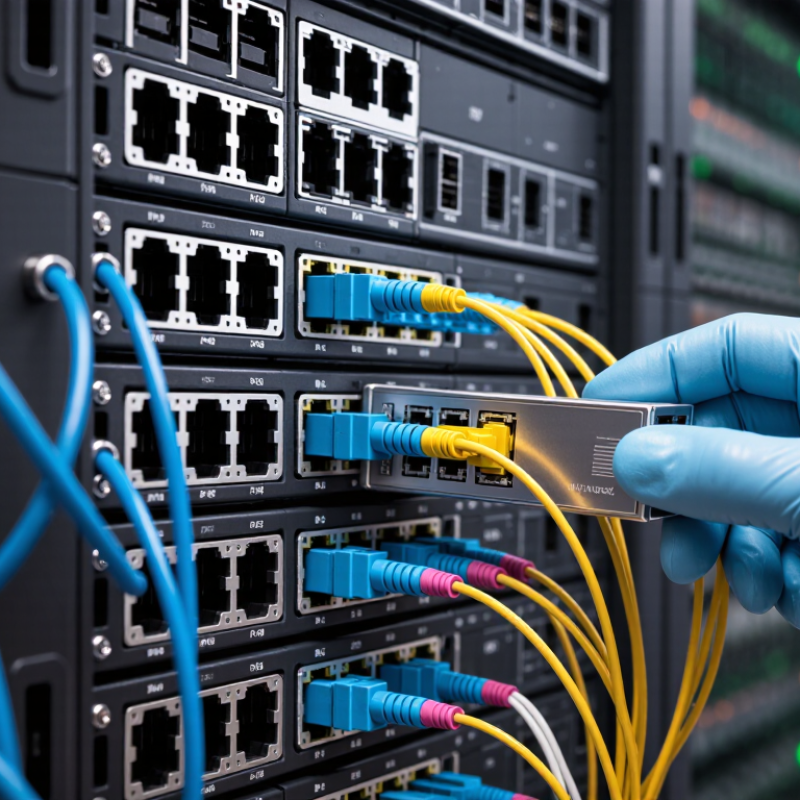
A fiber transceiver converts electrical signals into optical signals across a network link. Before selecting one, define its job clearly. Will it connect a switch to a server, extend a building link, or support a data center spine? The answer determines speed, reach, fiber type, wavelength, and connector choice. Do not start with price.

Measure the actual link, not the distance shown on a floor plan. Check whether the cable is multimode or single-mode, and verify its core size when available. Then match the transceiver’s data rate, transmission distance, and port standard. A module rated for 10 gigabits per second may not suit a 1-gigabit port. Likewise, a long-range module can be unnecessary for a short office connection. Keep it practical.

In field deployments, small mismatches often cause the biggest delays. A link may match the speed but fail because of the wrong fiber type or wavelength. Confirm duplex operation, connector style, power limits, and operating temperature. Inspect connector cleanliness and test the link with an optical power meter when possible. Document the selected specifications for future maintenance. I have found that this step is often skipped, and that is a weakness. Network plans change, so a carefully recorded choice may still need review later.

Match Fiber Type, Wavelength, and Transmission Distance

Choosing the right fiber transceiver starts with the fiber already installed. Multimode fiber suits short connections inside data centers and campus buildings. It commonly uses 850 nm light. Single-mode fiber supports longer distances and usually operates at 1310 nm or 1550 nm. Check the cable label, not memory. OM3 and OM4 cables can look nearly identical.

Transmission distance is not only a number on a product sheet. Fiber length, connector loss, splices, bends, and temperature can reduce the available optical budget. A 10-kilometer rating may fail on a poorly maintained route. Measure the actual path, then compare its loss with the transceiver’s transmitter and receiver limits. Leave some margin. Too little margin creates unstable links that are difficult to diagnose.

Wavelength matching also matters. The transceiver and fiber must support the same optical range. Bidirectional links may use different wavelengths in each direction, so both ends require the correct pair. I have seen planning focus on distance while ignoring connector type and fiber mode. That shortcut is tempting, but it can waste time and hardware. When specifications seem unclear, verify them with an optical power meter and the equipment manual. Small tests beat confident assumptions.

How to Choose the Right Fiber Transceiver?

Match the fiber type, wavelength, and transmission distance to the optical standard. The chart shows typical maximum Ethernet reach values for common multimode and single-mode combinations.

At 10 Gb/s, 850 nm multimode optics provide shorter reaches that depend on the OM grade, while 1310 nm single-mode optics can reach approximately 10 km over OS2 fiber. Values are based on commonly specified Ethernet optical-reach limits.

Compare Speed, Connector, and Form-Factor Compatibility

How to Choose the Right Fiber Transceiver?

Compare Speed, Connector, and Form-Factor Compatibility

Choosing a fiber transceiver starts with the network’s actual speed. A 1G module cannot replace a 10G module. Check the switch port, server adapter, and required data rate together. During field installations, I have seen teams choose by distance alone. That approach caused unexpected link failures. Speed must match at both ends.

Connector type matters just as much. LC connectors suit many duplex links and use little rack space. SC connectors are larger and easier to handle with gloved hands. MPO connectors support high-density parallel connections, but polarity and fiber counts require careful checking. Confirm whether the cable uses single-mode or multimode fiber. Wavelength and transmission distance must also match. Small details matter.

Form factor creates another compatibility test. SFP, SFP+, SFP28, and QSFP modules may serve different speeds and port designs. A module can fit physically but still fail through software restrictions or unsupported coding. Read the equipment datasheet before ordering. Check temperature ratings for cabinets with limited airflow. I once trusted a similar-looking module and overlooked power requirements. That mistake was avoidable. Leave room for verification, because product descriptions are not always precise. Record the port type, speed, connector, fiber type, reach, and operating temperature before installation.

How to Choose the Right Fiber Transceiver? - Compare Speed, Connector, and Form-Factor Compatibility

Fiber Transceiver Compatibility Comparison
Ethernet Standard Nominal Speed Common Optical Type Fiber Type Typical Wavelength Maximum Reach Connector Typical Form Factor Duplex or Parallel Optics Best-Fit Application Key Compatibility Check
1000BASE-SX 1 Gb/s Short-range multimode OM1, OM2, OM3, or OM4 multimode fiber 850 nm Up to 275 m on OM1; up to 550 m on OM2, OM3, or OM4 Duplex LC is common SFP Duplex, two fibers Building networks, data-center access, and short interconnects Use multimode fiber and verify that the switch supports a 1 Gb/s SFP optic.
1000BASE-LX 1 Gb/s Longer-range singlemode or multimode OS1 or OS2 singlemode; can operate on multimode with a mode-conditioning cable in some installations 1310 nm Up to 10 km on singlemode fiber Duplex LC is common SFP Duplex, two fibers Campus links, building-to-building connections, and longer 1 Gb/s uplinks Confirm the installed fiber type and the required optical distance before selecting the optic.
10GBASE-SR 10 Gb/s Short-range multimode OM3 or OM4 multimode fiber recommended 850 nm Up to 300 m on OM3; up to 400 m on OM4 Duplex LC is common SFP+ Duplex, two fibers Top-of-rack links and short data-center connections Do not use it for singlemode-only infrastructure without confirming optical compatibility.
10GBASE-LR 10 Gb/s Long-range singlemode OS1 or OS2 singlemode fiber 1310 nm Up to 10 km Duplex LC is common SFP+ Duplex, two fibers Data-center interconnects, campus backbones, and metropolitan links Check the host port for SFP+ support and ensure the link budget covers the installed distance.
25GBASE-SR 25 Gb/s Short-range multimode OM3 or OM4 multimode fiber 850 nm Up to 70 m on OM3; up to 100 m on OM4 Duplex LC is common SFP28 Duplex, two fibers High-density server access and short data-center leaf-spine links A 25 Gb/s SFP28 port is required; an SFP+ host port may not support 25 Gb/s operation.
25GBASE-LR 25 Gb/s Long-range singlemode OS2 singlemode fiber 1310 nm Up to 10 km Duplex LC is common SFP28 Duplex, two fibers Longer 25 Gb/s server, campus, and aggregation links Verify that the switch, network card, and transceiver all support the same 25 Gb/s Ethernet mode.
40GBASE-SR4 40 Gb/s Short-range parallel multimode OM3 or OM4 multimode fiber 850 nm Up to 100 m on OM3; up to 150 m on OM4 Multifiber push-on connector, typically MPO-12 QSFP+ Parallel optics, typically 4 transmit and 4 receive lanes Short data-center backbone and switch-to-switch connections Confirm MPO polarity, fiber-pair mapping, lane breakout requirements, and connector gender.
40GBASE-LR4 40 Gb/s Long-range wavelength-division multiplexed singlemode OS2 singlemode fiber Four wavelengths near 1310 nm Up to 10 km Duplex LC is common QSFP+ Duplex fiber with four multiplexed optical lanes Long-distance 40 Gb/s uplinks and campus backbones Unlike SR4, it normally uses duplex LC cabling rather than an MPO trunk.
100GBASE-SR4 100 Gb/s Short-range parallel multimode OM3 or OM4 multimode fiber 850 nm Up to 70 m on OM3; up to 100 m on OM4 MPO-12 is common QSFP28 Parallel optics, four optical lanes High-density data-center switch and server interconnects Check MPO polarity, lane order, and whether the link uses a parallel or breakout architecture.
100GBASE-CWDM4 100 Gb/s Short-to-medium-range wavelength-division multiplexed singlemode OS2 singlemode fiber Four wavelengths around 1310 nm Up to 2 km Duplex LC is common QSFP28 Duplex fiber with four multiplexed optical lanes Data-center interconnects longer than multimode reach Use duplex singlemode cabling; it is not a direct replacement for an MPO-based SR4 link.
100GBASE-LR4 100 Gb/s Long-range wavelength-division multiplexed singlemode OS2 singlemode fiber Four wavelengths around 1310 nm Up to 10 km Duplex LC is common QSFP28 Duplex fiber with four multiplexed optical lanes Campus, metro, and long data-center backbone links Verify host-port support, duplex LC cabling, and the required optical power budget.
400GBASE-DR4 400 Gb/s Short-range parallel singlemode OS2 singlemode fiber 1310 nm, using four optical lanes Up to 500 m MPO-12 or equivalent multifiber connector QSFP-DD or OSFP, depending on host equipment Parallel optics, four 100 Gb/s lanes High-capacity data-center spine and switch interconnects Form factor, lane breakout, MPO polarity, and host electrical interface must all match.

Quick Selection Rules

  • Match the speed first: The transceiver data rate must be supported by the switch, router, server adapter, or other host port.
  • Match the fiber type: Multimode optics are generally used for short distances, while singlemode optics support longer links.
  • Match the connector and cabling: LC usually indicates a duplex two-fiber connection; MPO commonly indicates a multifiber parallel-optics connection.
  • Match the form factor: SFP, SFP+, SFP28, QSFP+, QSFP28, QSFP-DD, and OSFP are mechanically and electrically different families.
  • Check reach and optical budget: The rated distance depends on fiber grade, attenuation, connector loss, splice loss, and the transceiver's transmit and receive specifications.
  • Do not mix optical types casually: Two transceivers at the same speed may still be incompatible if their wavelengths, fiber types, connectors, lane layouts, or host interfaces differ.

Evaluate Environmental Conditions, Standards, and Reliability

Choosing the right fiber transceiver starts with the environment, not the product list.

Check the cabinet temperature during peak traffic, not only the room temperature. Heat accumulates. Dust matters.

A sealed outdoor enclosure may require wider operating temperatures, stronger humidity protection, and suitable surge precautions. In a clean data room, those features may add cost without improving performance.

Also measure link distance, fiber type, connector loss, and available power before selecting transmission speed or optical reach. A transceiver that works on a laboratory bench can fail inside a hot, crowded rack.

Standards provide a reliable basis for comparison.

Confirm Ethernet compatibility with the required IEEE 802.3 specification, then review optical safety requirements under IEC 60825-1.

Environmental testing aligned with IEC 60068 can reveal resistance to vibration, temperature changes, and moisture.

Verify digital diagnostics, alarm thresholds, and documented test results rather than trusting a simple compliance label.

In field installations, I have found that clean connectors and accurate power budgets prevent more failures than impressive specifications.

I once underestimated airflow around a compact switch, and intermittent links appeared only in the afternoon. That mistake changed my inspection routine.

Reliability should include traceable quality control, realistic aging tests, and clear replacement procedures.

Perfect planning is unlikely; measured assumptions are better.

Verify Interoperability, Budget, and Long-Term Support

How to Choose the Right Fiber Transceiver?

Verify Interoperability, Budget, and Long-Term Support

Choosing a fiber transceiver starts with interoperability, not price. Match the data rate, wavelength, fiber type, connector, and transmission distance. A 10G single-mode module may list 1310 nm and 10 km. Those figures still do not guarantee stability. Check the switch port standard, duplex requirements, optical power range, and diagnostic support. Confirm whether the host accepts third-party coding. A perfect optical match can still fail at the software layer.

Budgeting requires more than the purchase price. Compare power consumption, installation labor, testing time, replacement stock, and expected failure rates. A cheaper module becomes expensive when technicians revisit a 300-meter cable run. Request test reports or an interoperability matrix before ordering dozens of units. Keep one spare pair from the same production batch for critical networks. Small details matter. In real deployments, clean specifications have still failed because the host rejected the module.

Long-term support deserves a written answer. Ask how long firmware compatibility, warranty service, and technical documentation will remain available. Check whether matching units can be provided after a platform refresh. Avoid relying on vague promises. Yet careful planning has limits. Fiber routes change, equipment ages, and assumptions become outdated. Recheck compatibility during every major upgrade. Record serial numbers, optical data, and measured loss in the maintenance log.